What Is a Turn Mill CNC Machine and How Does It Work?
A Turn-Mill Cnc Machine combines turning and milling operations in one computer-controlled platform. It can rotate a workpiece, cut its diameter, drill holes, mill flats, and create complex contours without repeated setup. In a typical cycle, the spindle holds the material while driven tools approach from different angles. The CNC control converts programmed coordinates into synchronized movements. Coolant flows across the cutting zone, carrying heat and chips away from the tool tip.
This capability matters because every transfer between machines can introduce alignment errors, handling time, and additional inspection work. The International Federation of Robotics’ World Robotics 2024 report recorded 541,302 industrial robots installed worldwide in 2023. That figure reflects a broader movement toward automated, repeatable production. CNC equipment supports this movement, especially when manufacturers need consistent parts for aerospace, medical, automotive, and precision-engineering applications. AMT’s U.S. Manufacturing Technology Orders report also remains a useful industry reference for tracking capital investment in advanced production equipment.
The practical value becomes clear on a shop floor. A steel shaft may be faced, turned to size, drilled, and milled with a keyway in one secured setup. That can reduce handling, but it does not remove every risk. Poor tool offsets, unstable workholding, or incorrect cutting data can still damage a part within seconds. The machine is powerful, not independent. Operators must understand work coordinates, tool wear, chip control, and inspection requirements. Some explanations make turn-mill production sound effortless. That assumption is too neat. Real performance depends on programming quality, machine rigidity, material behavior, and disciplined process control.
What Is a Turn Mill CNC Machine?
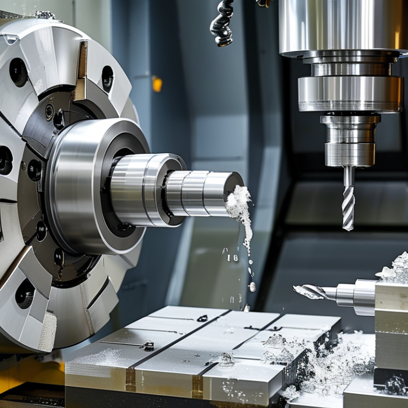
A turn mill CNC machine combines turning and milling in one computer-controlled platform. The workpiece rotates like it would on a lathe. Driven tools can also rotate and cut slots, holes, flats, and complex contours. This arrangement often completes several operations in one setup. That matters when alignment is critical.
In practical use, a chuck holds the raw bar or billet. The main spindle controls rotational speed and cutting position. A secondary spindle may transfer the part for back-side machining. Linear and rotary axes guide tools along programmed paths. Operators usually load a digital program, set tool offsets, and verify the first component carefully. One small offset error can spoil an expensive workpiece.
According to Grand View Research, the global CNC machine market was valued at about USD 88 billion in 2023. Its report also forecasts strong growth through 2030, driven by automation and tighter production demands. Turn-mill equipment fits this trend by reducing handling, setup time, and work-in-process inventory. Manufacturing engineers commonly evaluate cycle time, spindle power, tool access, and achievable tolerance before selecting a machine. In my experience, fewer setups can improve consistency, but they do not guarantee it. Programming becomes harder. Tool interference remains a real risk. Some machines also sacrifice maximum turning capacity for milling flexibility. The best choice depends on part geometry, batch size, material, and inspection requirements.
Key Components and Their Functions
A turn mill CNC machine combines turning and milling in one controlled setup. The workpiece is held by a chuck and rotated by the main spindle. Cutting tools remove material as the spindle maintains programmed speed and torque. This arrangement reduces repeated clamping, which can improve alignment between features.
The turret stores several tools and moves them into cutting position. Turning tools shape outside diameters, shoulders, and grooves. Live tooling rotates drills, end mills, and taps for cross-holes or slots. Linear axes guide tool movement along the part, while the control system coordinates every position, speed, and feed command. A steady tool path matters. Small errors can still create visible marks.
Coolant carries heat away and helps clear chips from the cutting zone. An enclosed work area protects operators from hot fragments and improves chip management. Probes may measure tool length, workpiece position, or finished dimensions during production. In my experience, accurate probing cannot rescue a poorly secured part. Setup remains critical. Even a clean drawing may require adjustment after the first test cut, because material behavior, tool wear, and clamping pressure rarely match assumptions perfectly.
Turn Mill CNC Machine: Controlled Axes by Machining Function
The chart shows the minimum number of coordinated axes commonly associated with each machining function. X and Z axes control turning movements, the C-axis rotates the workpiece for indexed or synchronized machining, the Y-axis enables off-center milling, and the B-axis provides tool-orientation capability for advanced 5-axis work.
Common Operations and Applications
What Is a Turn Mill CNC Machine and How Does It Work?
Common Operations and Applications
A turn mill CNC machine combines turning and milling in one controlled setup. The workpiece rotates on the spindle, while driven tools cut its surface. It can perform facing, contour turning, grooving, drilling, boring, tapping, and thread milling. C-axis and Y-axis movement can also produce flats, cross-holes, slots, and angled features. Fewer setups usually mean better alignment and shorter handling time.
This capability suits compact, complex parts. Typical applications include hydraulic fittings, aircraft connectors, surgical components, shafts, and energy-system hardware. A 2024 report from the International Federation of Robotics recorded 541,302 new industrial robots installed worldwide in 2023. That figure reflects growing automation demand, although robot growth does not directly measure turn mill machine sales. Industry studies also identify multitasking equipment as a way to reduce work-in-progress and improve machine utilization. The result depends heavily on programming quality, tooling, and inspection discipline.
Tips: Match the toolpath to the material before chasing speed. Use rigid workholding and verify tool clearance in simulation. Check chip evacuation around deep holes. Measure the first part carefully. A turn mill machine can save a setup, but it cannot correct poor process planning. I have found that reducing cycle time too aggressively often creates heat, burrs, or unstable finishes. Review cutting data from recognized tooling and manufacturing reports, then validate it on the actual machine.
Advantages and Limitations of Turn Mill CNC Machines
What Is a Turn Mill CNC Machine and How Does It Work?
A turn mill CNC machine combines turning and milling in one automated setup. The workpiece rotates like a lathe, while powered tools cut slots, holes, flats, and complex profiles. Live tooling, turret movement, and computer-controlled axes coordinate these operations. This design can produce a finished component with fewer transfers between machines.
Its main advantage is reduced setup time. Fewer re-clampings can improve positional accuracy and reduce handling marks. One machine may complete a shaft with threads, cross-holes, and milled faces. Production also becomes more consistent because programs control tool paths and cutting speeds.
However, turn mill machines cost more than basic lathes. Programming is more demanding, and operators need strong knowledge of workholding, tooling, and process planning. A complex machine can also create complex mistakes. Poor tool selection may cause vibration, heat, or uneven surface finish. Maintenance and calibration require careful records. The machine is powerful, but not always economical for simple parts.
Tips: Confirm the part geometry before choosing this equipment. Review cycle time, tolerance, and tool access. Use simulation to check collisions. Measure the first part carefully, then adjust only verified values. Small errors grow quickly. A practical trial run can reveal problems that a drawing does not show.
 English
  Česká republika
 Deutsch
 Dutch
Dutch Polska

